Digital to Analog Converter (DAC) from 0 to 10V
Published by Weisser Zwerg Blog on
Manually via Potentiometer or Remote Controlled via RS485, Pulse Width Modulation (PWM) or the I2C Bus
Rationale
Sometimes you need to be able to control devices that react to a voltage setting between 0 to 10V. Initially, I thought, this should be simple and there would be ready made devices out there that can be used for these situations. But, as far as I can tell at the moment, I was wrong. This is far from being simple and the below is a list of options that I found and evaluated.
Besides the core tasks of being able to control a voltage output between 0 and 10V several additional challenges popped up that I also initially imagined to be trivial. I wanted to control the controllable devices via a Raspberry Pi 4B via a Jupyter notebook in Python. The first step in that direction is to enable the pulse width modulation and the I2C bus communication capabilities on the Raspberry Pi and then find a library that does the job. While there is a lot of documentation out there for the Raspberry Pi, most of it is outdated for older Raspberry Pis. Therefore, it is difficult to find the current, valid documentation via Google in the jungle of old and outdated documentation. I even tried to use ChatGPT and the new Microsoft Bing Chat search, but I still got wrong answers with a very confident voice of being correct.
Device Gallery


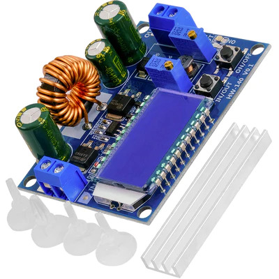
- HW-140 DC-DC Buck Boost Converter
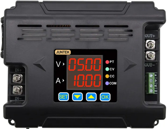
- JUNTEK DPM8624 60V24A Programmable DC DC Step Down Power Supply Buck Converter with RS485 communication
- PWM Signal to 0-10V D/A Digital Analog SPS Module
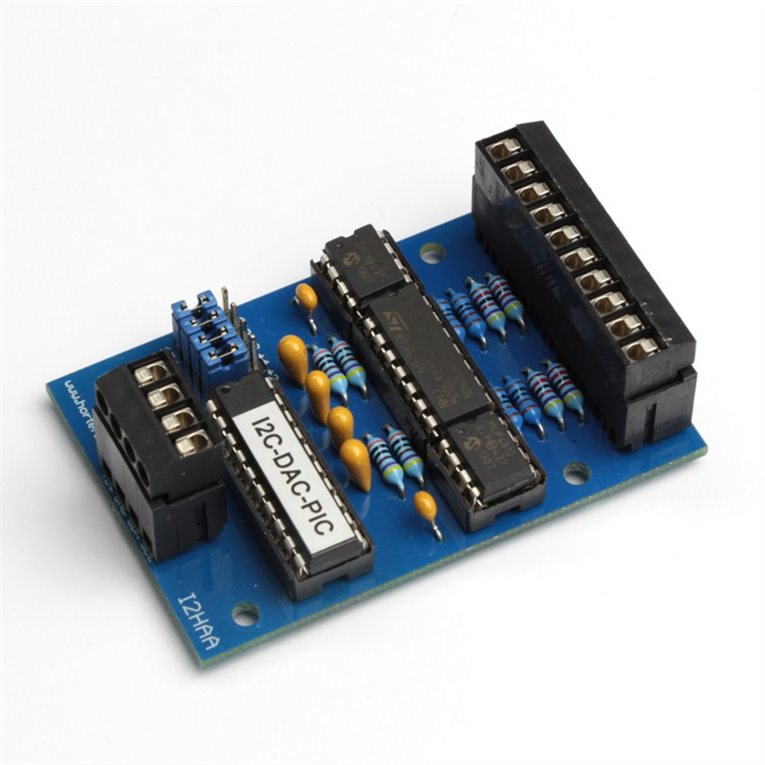
- I2HAA I2C Analog Output Module 4 Channel 10 Bit
- Include the solder service if you don’t want to assemble it yourself.
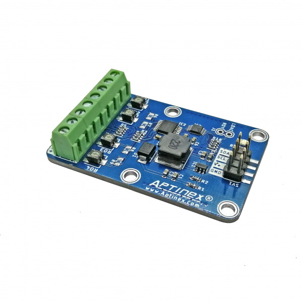
- Aptinex 4 Channel DAC Module DA4C010BI I2C Digital to Analog 0-10V MCP4728
Devices I had a look at but did not buy:
I’ve searched for these devices over a period of 9 months and only came up with such a short list. In addition, these devices are far from being a consumer device like a Shelly or a Sonoff. I was dreaming of a device like the 4CHR3 4-gang Wi-Fi Smart Switch from Sonoff, but just for analogue 0 to 10V outputs. That seems to remain a dream …
Power Supply
Most of the devices I look at are step-down converters, e.g., they can only reduce the voltage from a higher source input voltage. You will therefore need a power supply that delivers this input voltage. Two options I looked at are:
- Standard 12V Power Supply
- 100W Typ C Dc Power Adapter
- Together with a Baseus 100 W, PD Power Supply USB C (USB-PD)
- I learned about USB-PD and how it works in the BitBastelei #503 - USB-PD in DIY-Projekten nutzen YouTube video.
- A USB 3,1 Typ-C Tester can help to get more insight into what is going on.
In both cases these 12V Plug 2,1mm x 5,5mm DC Male and Female adapters help to connect the output power to Dupont connectors / Jumper Wire Cables.
The Manual Way
The most straight forward manual approach is to use a Laboratory Power Supply. There, you can adapt the voltage and also configure a current limiter if needed.
The HW-140 DC-DC Buck Boost Converter is in principle a mini laboratory power supply. There are two potentiometers on it via which you can configure the output voltage, but also a current limit if needed. The interesting thing here is that this device is a step-down and a step-up converter at the same time in one device. Most of the other devices are step-down converters only.
Just as a side remark: Initially, when I first saw step-up converters, I was puzzled how these devices work. In case you’re also surprised and would like to know more about the details I can recommend the following video: How Boost Converters Work (DC-DC Step-Up) - Electronics Intermediate 1
Python environment
On my normal desktop PCs, I like to work with the micromamba environment to set-up my
Python environments. On the Raspberry Pi I ran into an illegal instruction error when running pip to install packages. After quite some digging and
some luck, I found out that the problem is due to the anaconda channels I had configured. It seems that only the conda-forge channel supports the
arm64 platform. I added a comment on Stack Overflow in the Raspberry pi pip install illegal instruction
erorr issue.
To make a long story short: You can avoid all these problems by starting off of miniforge. miniforge
seems to configure the conda-forge channel by default and avoids this problem.
Control via RS485
The JUNTEK DPM8624 60V24A Programmable DC DC Step Down Power Supply Buck Converter with RS485 communication is by far the most powerful device in my list from above. It is in principle a programmable laboratory power supply, just not from AC to DC, but from DC to DC. If you go to the AliExpress web-site and scroll down you will find the link to the DPM8600_EN_manual.pdf. You can find an overview of all documents at http://68.168.132.244/DPM8600/material.html among which is also a DPM8600 series communication protocol in English.
The variant of the DPM8624 that I have is controllable via a RS485 interface and it came along with a USB to RS485 Converter Adapter.
It took me quite some time to understand, but it seems that the three protocols UART, RS232 and RS485 are all the same except that the voltage levels are different. The Universal Asynchronous Receiver Transmitter (UART) protocol seems to be adapted to transistor semiconductor voltage levels (TTL stands for Transistor-Transistor Logic) like 3.3V or 5.0V. The minimum and maximum voltages of RS-232 signals are +/- 13V. RS485 uses a voltage differential of ±7 V on top of the 0–5 V signal range. The GND for RS485 seems to be optional. Many USB to RS485 Converter Adapters only have two wires without a GND. If the GND wire is present then GND on both sides should be connected.
To understand the core of what the protocol does I can recommend the video The RS-232 protocol.
Once you have hooked up the RS485 Converter Adapter to your Linux computer you have to use a terminal emulation program like
picocom. You can use picocom in interactive mode or as a shell command. To read the current configured
voltage of the device you via the “Simple Communication Protocol” execute:
> picocom --baud 9600 --echo --imap crcrlf /dev/ttyUSB0 :01r10=0
If you work in manual mode and you did not configure the input map (–imap) you need to send a line feed (LF) character to end the command. CTRL-J sends this.
The python equivalent looks as follows:
import serial

com_port = serial.Serial('/dev/ttyUSB0')
com_port.baudrate = 9600 # set Baud rate to 9600
com_port.bytesize = 8    # Number of data bits = 8
com_port.parity   = 'N'  # No parity
com_port.stopbits = 1    # Number of Stop bits = 1

s = ':01r10=0\r\n'
encoded=s.encode('ascii')
data=bytearray(encoded)
# data0 = bytearray(b':01r10=0\r\n')
# Returns: Number of bytes written.
no = com_port.write(data)

data_in = com_port.readline()
print(data_in)
# b':01r10=1600.\r\n'
print(data_in.decode('ascii').strip())
# :01r10=1600.

com_port.close()
In a similar way you can send all the other commands that the device supports.
Control via Pulse Width Modulation (PWM)
The device PWM Signal to 0-10V D/A Digital Analog SPS Module reacts to Pulse Width Modulation (PWM). Within limits, it is not important at what frequency you transmit, but only the fraction of time the signal is on vs. the faction of time the signal is off. I used 1kHz for my experiments.
Before you can work with hardware pulse width modulation on the Raspberry Pi you have to configure the kernel to enable it. It seems that the embedded
Linux community came up with something called Device Tree Overlays (dtoverlay). This is configured on the Raspberry Pi i the /boot/config.txt
file. I first was not sure if these dtoverlay statements are additive, but they are, e.g., you can write several of them in one file and all of them
will take effect. You can read what the settings mean in the /boot/overlays/README file. I did put dtoverlay=pwm in my /boot/config.txt file and
rebooted. After that GPIO pin 18 is available for hardware pulse width modulation. One of the very few articles that I found by googling that actually
was helpful was Grundlagen der Pulsweitenmodulation, but
it uses different “functions” to what the /boot/overlays/README file said on my Raspberry Pi. This is why I simply stick to the most basic
configuration without specifying any further configuration details and simply hope that the defaults are good.
The naming of Raspberry Pi pins is a mess. You can have a look at https://pinout.xyz/ to find out which pin is GPIO 18. The PWM signal will be available between GND and GPIO 18.
You can control the hardware PWM via the files in /sys/class/pwm/pwmchip0/pwm0. The below is setting up a 50% duty cycle at 1kHz. The times given
are in nano seconds, e.g., 1000000 nano seconds are 1 milli second and correspond to 1kHz.
pi@raspberrypi:~ $ sudo su
root@raspberrypi:/home/pi# cd /sys/class/pwm/pwmchip0/
root@raspberrypi:/sys/class/pwm/pwmchip0/# echo 0 > export
root@raspberrypi:/sys/class/pwm/pwmchip0/# cd pwm0
root@raspberrypi:/sys/class/pwm/pwmchip0/pwm0# echo 1000000 > period
root@raspberrypi:/sys/class/pwm/pwmchip0/pwm0# echo  500000 > duty_cycle
root@raspberrypi:/sys/class/pwm/pwmchip0/pwm0# echo 1 > enable
You could add the line echo 0 > /sys/class/pwm/pwmchip0/export int your /etc/rc.local file, so that after every reboot the pwm0 device is
available for you.
Control via I2C Bus
Both the I2HAA I2C Analog Output Module 4 Channel 10 Bit and the Aptinex 4 Channel DAC Module DA4C010BI I2C Digital to Analog 0-10V MCP4728 devices are controlled via the I2C bus.
To learn more about the inner workings of the I2C bus I can recommend:
- Wie funktioniert I2C, einfach erklärt! from Edi’s Techlab
- I2C with Arduino and Raspberry Pi - Two Methods from DroneBot Workshop
Another good source is the 4 part tutorial starting at I2C Part 1 - Introducing I2C.
The second video above also explains how to enable the I2C bus on the Raspberry Pi via the raspi-config command. This command is uncommenting a line
in the /boot/config.txt file we encountered above already. You should add a further parameter to this file like dtparam=i2c_baudrate=400000 with a
baud rate that is supported by your I2C device. The valid settings here should be part of the device documentation.
The second video above also mentions that you can connect a 3.3V master device like the Raspberry Pi to a 5V slave device like the I2HAA,
e.g., connect the 3.3V from the Raspberry Pi to the 5V input of the I2HAA and it will work without a logic level shifter.
Once you have set-up your Raspberry Pi and have connected the device to your I2C bus you should check if it is detected:
> sudo apt install i2c-tools
> sudo i2cdetect -y 1
You should see an output similar to what is shown at I2C Part 2 - Enabling I²C on the Raspberry Pi.
For me the Horter I2HAA reacted at 0x58 and the Aptinex reacted at 0x64.
The best way to see how the Horter I2HAA is programmed is to read the I2C-Analog Output 4 Kanäle 0-10V 10 Bit blog post. For the Aptinex device you will have to download their library from their web-site and look at the code.
When you search for I2C and Raspberry Pi you automatically get directed to the smbus library. Only after a lot of failed attempts and a lot of
searching I found the little sentence in Raspberry Pi: I2C-Konfiguration und
-Programmierung that says:
A modification of I2C is the SMBus, the System Management Bus. In terms of hardware, it is identical to I2C, but defines a different transmission protocol on it.
Whenever I looked at how you program an I2C bus on an Arduino or another MCU board you only specified an address and a byte sequence to send over the
bus to the device. The smbus functions all take a cmd argument in addition to a bus
address and the byte or byte sequence (e.g. write_i2c_block_data(addr,cmd,vals)). I was not able to make any smbus library (the original or newer
ones like smbus2) work with the Horter or Aptinex devices. Also the i2c-tools command line tools did not work. Only, once I switched to the
pigpio library and its i2c_write_device(handle, data)
function, suddenly things started to work out.
2023-10-23 Update: First of all, there is not only one smbus library, but several as you can see on PyPI.
Have a look at https://github.com/ControlEverythingCommunity/AD5254/blob/master/Python/AD5254.py There you can see how to use the smbus-cffi library for i2c communication. You use thewrite_i2c_block_datamethod. But othersmbuslibraries seem to offer that method aswell, e.g. the smbus2 libarary.
Sadly, the pigpio library is not really a library, but a daemon running in the background and the
python library is only talking to that daemon via http and port 8888. And because things need to continue to be difficult the port 8888 conflicts with
the Jupyter notebook running by default on port 8888. So, you should pay attention to first start the pigpiod daemon and only then start-up the
Jupyter notebook (or invest more time reading the pigpiod documentation to find out how to start it at another port).
The other issue is that pigpio is not pip-installable, but you have to download it and install it via make. Just follow the instructions as given
on the web-site. Once you’ve gone through all of the steps execute in addition:
pi@raspberrypi:~/pigpio-master $ conda activate py310pi
pi@raspberrypi:~/pigpio-master $ pip install -e .
The first line activates the conda environment you use. The second line installs the “editable” version of the package in the conda environment. After
these two steps, starting the pigpiod daemon and installing the python library into your conda environment, you should be able to work with the i2c
devices as follows:
import pigpio

pi = pigpio.pi()

handle = pi.i2c_open(1, 0x58)

def horter_byte_sequence(channel, voltage):
    voltage = int(voltage * 100.0)

    output_buffer = bytearray(3)

    high_byte = voltage >> 8
    low_byte  = voltage & 0xFF;
    output_buffer[0] = (channel & 0xFF)
    output_buffer[1] = low_byte
    output_buffer[2] = high_byte

    return output_buffer

v = horter_byte_sequence(0, 5.0)
pi.i2c_write_device(handle, v)
The equivalent function for the Aptinex device looks like:
MCP4728_I2CADDR_DEFAULT  = 0x64

MCP4728_MULTI_IR_CMD     = 0x40
MCP4728_MULTI_EEPROM_CMD = 0x50
MCP4728_FAST_WRITE_CMD   = 0xC0

MCP4728_VREF_VDD      = 0
MCP4728_VREF_INTERNAL = 1

MCP4728_GAIN_1X = 0
MCP4728_GAIN_2X = 1

MCP4728_PD_MODE_NORMAL   = 0 # Normal; the channel outputs the given value as normal.
MCP4728_PD_MODE_GND_1K   = 1 # VOUT is loaded with 1 kΩ resistor to ground. Most of the channel circuits are powered off.
MCP4728_PD_MODE_GND_100K = 2 # VOUT is loaded with 100 kΩ resistor to ground. Most of the channel circuits are powered off.
MCP4728_PD_MODE_GND_500K = 3 # VOUT is loaded with 500 kΩ resistor to ground. Most of the channel circuits are powered off.

def setChannelValue(channel, new_value, new_vref = MCP4728_VREF_VDD, new_gain = MCP4728_GAIN_1X, new_pd_mode = MCP4728_PD_MODE_NORMAL, udac = False):
    address = 0x64

    channel = int(channel)
    new_value = int(new_value)
    new_vref = int(new_vref)
    new_gain = int(new_gain)
    new_pd_mode = int(new_pd_mode)
    udac = 1 if udac else 0

    output_buffer = bytearray(3)

    sequential_write_cmd = MCP4728_MULTI_IR_CMD
    sequential_write_cmd |= (channel << 1);
    # sequential_write_cmd |= udac;
    output_buffer[0] = sequential_write_cmd;

    new_value |= (new_vref << 15);
    new_value |= (new_pd_mode << 13);
    new_value |= (new_gain << 12);
    output_buffer[1] = new_value >> 8;
    output_buffer[2] = new_value & 0xFF;
    return output_buffer
This is a verbatim translation from the provided C++ class to python, but I did not extensively test it yet.
Summary
I hope the above will help others to achieve their goals quicker than I did. If you have any additional remarks, please use the commenting function below. And if you know about a consumer device like a Shelly or a Sonoff that does the job then please drop me a note, too.
Update 2023-04-10
Consumer Device: Homematic IP Universal Schaltaktor - 0‑10 V
At the beginning of my home automation journey I decided that I wanted to use WLAN for mains powered
devices and Zigbee (and in the future Matter, the more or
less successor of Zigbee) for battery powered devices, as these are open and world wide standards with a broad industry support and that can be
integrated into any home automation system like Home Assistant. Therefore, I never looked at solutions like
eQ-3 Homematic IP with its proprietary 868 MHz wireless protocol. But it seems that there is a Homematic IP
consumer device to output a remote controllable 0 to 10 V signal called Universal Schaltaktor - 0‑10
V.
I started to look into the eQ-3 Homematic IP solution and think that this system is not as closed as I first thought. There are open-source alternatives to its control unit called CCU:
- RaspberryMatic (github)
- Installation Docker OCI
- HomeAssistant Integration: via the HACS community add-on custom_homematic.
- debmatic
As far as I understand you can use the HomeAssistant
Integration for any control unit like
CCU3 / CCU2 / RaspberryMatic / debmatic /
piVCCU. You only have to set the IP address of the control unit in step 8 of the set-up process.
Here I found a description of the core difference between RaspberryMatic and debmatic:
The big difference is that RaspberryMatic is a BuildRoot system where the user cannot install any additional software (except for the CCU addons), while debmatic is based on a Debian based system (such as Debian, Ubuntu, Raspberry Pi OS, Armbian) and then you have all the freedom that the OS gives you. And with debmatic I aimed right from the start to bring the CCU to normal PC hardware, when Jens still categorically ruled that out for RaspberryMatic because he thought that it didn’t make sense and only an independent control centre on a Raspberry or a Tinkerboard was stable.
But as far as I can tell RaspberryMatic is the system with the bigger user base. At least from the GitHub stars it looks that way. But both
systems seem to be actively maintained and supported.
Here is a YouTube video that explains the set-up process: RaspberryMatic AddOn auf Home Assistant installieren und einrichten 2022. It also talks about the hardware USB stick you will need to communicate via the proprietary 868 MHz protocol. If you prefer a written document you can find it at RaspberryMatic Add-on auf Home Assistant installieren 2022.
Besides this consumer device Universal Schaltaktor - 0‑10 V I also found another device that I was looking for: a Wandthermostat mit Schaltausgang to control the floor heating. You can buy it for 230V or 24V actuators (Stellantrieb), here for example at Amazon.
DMX/Art-Net based devices
A friend of mine made me aware that professional light technicians use 0-10V control signals and that they use DMX or Art-Net (the IP based transmission of DMX) to communicate with those devices. Here you can find more about the protocol: art-net.org.uk.
Here are some devices:
And here is a WLAN to DMX adapter:
Shelly RGBW2 LED controller: 4 channel PWM based led controller
Another available option might be the Shelly RGBW2. As far as I understand it works at 1kHz and needs a DC power supply, e.g., it can’t be connected directly to the AC power.
You can read more about it at: Shelly RGBW2 LED Strip Controller.
Update 2023-06-07
There is a thread Any device allowing control 0…10V DC? in the Home Assistant community forum. It mentions:

